13.6: Прийом
- Page ID
- 78666

Взагалі імпеданс ланцюга частково резистивний і частково реактивний:
\[\label{13.6.2}Z=R+jX.\]
Реальна частина - це опір, а уявна частина - реактивний опір. Відносини між\(V\) and \(I\) is \(V = IZ\). Якщо схема чисто резистивна,\(V\) and \(I\) are in phase. If is it purely reactive, \(V\) and \(I\) differ in phase by 90o. The reactance may be partly inductive and partly capacitive, so that
\[\label{13.6.3}Z=R+j(X_L+X_C). \]
Дійсно, таку систему ми докладно опишемо в наступному розділі. Зверніть увагу, що\(X_C\) є негативним.
Іноді пишеться еквація\(\ref{13.6.3}\)\(Z=R+j(X_L-X_C)\), in which \(X_C\) призначена для представлення кількості без знаку\(1/(C\omega)\). У цих примітках\(X_C\) покликана представляти\(-1/(C\omega)\).
Зворотний імпеданс\(Z\) is the admittance, \(Y\) .
Таким чином
\[\label{13.6.4}Y=\dfrac{1}{Z}=\dfrac{1}{R+jX}.\]
І звичайно, так як\(V = IZ,\, I = VY\) .
Всякий раз, коли ми бачимо комплексне (або чисто уявне) число у знаменнику виразу, ми завжди негайно множимо верх і низ на складний сполучений, тому Equation\ ref {13.6.4} стає
\[\label{13.6.5}Y=\dfrac{Z^*}{|Z|^2}=\dfrac{R-jX}{R^2+X^2}.\]
Це можна написати
\[\label{13.6.6}Y=G+jB,\]
де реальна частина\(G\), - провідність:
\[\label{13.6.7}G=\dfrac{R}{R^2+X^2},\]
і уявна частина,\(B\), is the susceptance:
\[\label{13.6.8}B=-\dfrac{X}{R^2+X^2}.\]
Одиницею SI для допуску, провідності та сприйнятливості є siemens (або «mho» у неформальній розмові).
Я залишаю це читачеві, щоб показати, що
\[\label{13.6.9}R=\dfrac{G}{G^2+B^2}\]
і
\[\label{13.6.10}X=-\dfrac{B}{G^2+B^2}.\]
Який імпеданс ланцюга нижче змінного струму частоти\(2000/\pi \text{ Hz}\) (\(\omega = 4000\text{ rad s}^{-1}\)) ?

Рішення
Думаю, що наступне буде з готовністю узгоджено. (Пам'ятайте, що допущення - це зворотний імпеданс; і, всякий раз, коли ви бачите комплексне число в знаменнику, негайно помножте верх і низ на сполучений.)
Імпеданс\(\text{AB} = (25 -50j)\)\(\Omega\)
Імпеданс\(\text{CD} = (40 + 10j)\)\(\Omega\)
Прийом\(\text{AB} = \dfrac{1+2j}{125} \text{ S} = \dfrac{6+12j}{750} \text{ S}\)
Прийом\(\text{CD} = \dfrac{4-j}{150} \text{ S} = \dfrac{20-5j}{750}\text{ S}\)
Допустимість ланцюга =\(\dfrac{26+7j}{750}\text{ S}\)
Імпеданс ланцюга =\(\dfrac{30(26-7j)}{29}\Omega\)
Струм веде по напрузі на 15º
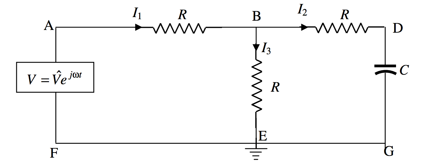
Три резистора і конденсатор підключені до\(\text{AC}\) voltage source as shown. The point \(\text{E}\) is grounded (earthed), and its potential can be taken as zero. Calculate the three currents, and the potential at \(\text{B}\).
Рішення
Ми можемо зробити це, використовуючи правила Кірхгофа звичайним способом. Коли я зробив це, я виявив, що алгебра трохи важка, і я виявив, що це було значно спрощено писати\(\dfrac{1}{C\omega}=aR\), where \(a\) is a dimensionless number. Then, instead of writing the impedance of the section BDG as \(R-\dfrac{j}{C\omega}\), я пишу це як\(R(1-ja)\).
Правила Кірхгофа, застосовані до двох контурів і точки\(\text{B}\), are
\[\label{13.6.11}V=I_1R+I_2R\]
\[\label{13.6.12}I_2(1-ja)-I_3=0\]
\[\label{13.6.13}I_1=I_2+I_3\]
Ці рівняння мають бути розв'язані для трьох струмів\(I_1,I_2,I_3\). These will all be complex numbers, representing alternating currents. Solution could proceed, for example, by eliminating \(I_3\) з рівнянь\ ref {13.6.11} і\ ref {13.6.12}, а потім виключені\(I_3\) з рівнянь\ ref {13.6.11} і\ ref {13.6.13}. Це призводить до двох рівнянь в\(I_1\) і\(I_2\). Ми можемо усунути\(I_1\) їх, щоб отримати\(I_2\). Я роблю його\(I_2=\dfrac{V}{R(3-2aj)}\), але потім відразу множимо верх і низ на,\(3+2aj\) щоб отримати
\[\label{13.6.14}I_2=\left ( \dfrac{3+2aj}{9+4a^2}\right ) \dfrac{V}{R}\]
Потім просто повернутися до вихідних рівнянь, щоб отримати
\[\label{13.6.15}I_1 = \left ( \dfrac{6+2a^2+aj}{9+4a^2}\right ) \dfrac{V}{R}\]
і
\[\label{13.6.16}I_3 = \left ( \dfrac{3+2a^2 -aj}{9+4a^2}\right ) \dfrac{V}{R}\]
Наприклад, припустимо, що частота і ємність були такими\(a = 1\), що , то
\[\label{13.6.17}I_1=\left ( \dfrac{8+j}{13}\right )\dfrac{V}{R}\]
\[\label{13.6.18}I_2=\left ( \dfrac{3+2j}{13}\right )\dfrac{V}{R}\]
і
\[\label{13.6.19}I_3=\left ( \dfrac{5-j}{13}\right )\dfrac{V}{R}\]
Таким чином\(I_1\) призводить\(V\) на 7º.1;\(I_2\) призводить\(V\) на 33º.7; і\(I_3\) відстає\(V\) на 11º.3.
Векторна (фазорова) діаграма для цих трьох струмів показана нижче, в якій фазон, що представляє змінну напругу\(V\) is directed along the real axis.

Маючи на увазі, що потенціал при\(\text{E}\) is zero, we see that the potential at \(\text{B}\) is just \(I_3R\) and is in phase with \(I_3\).
Є ще один метод пошуку\(I_1\) , який ми зараз спробуємо. Якщо ми отримаємо однакову відповідь обома методами, це буде гарною перевіркою на можливі помилки в алгебрі.
Я заново намалюю принципову схему наступним чином:
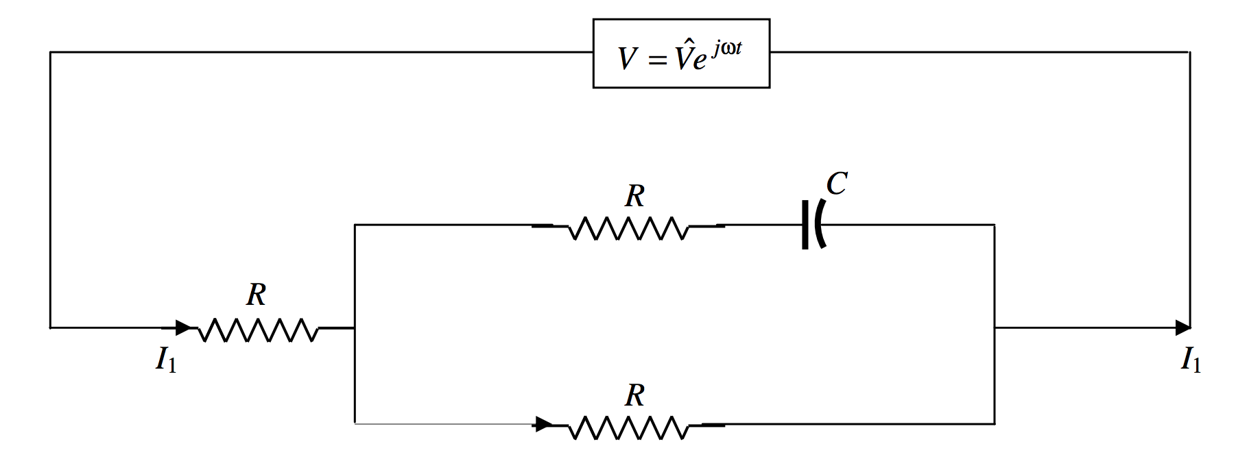
Розрахувати\(I_1\) we have to calculate the admittance \(Y\) of the circuit, and then we have immediately \(I_2=YV\). The impedance of \(R\) and \(C\) in series is \(R-jAR\) and so its admittance is \(\dfrac{1}{R-jaR}\). The admittance of the rectangle is therefore \(\dfrac{1}{R-jaR}+\dfrac{1}{R}=\dfrac{1}{R}\cdot \left [ \dfrac{2-ja}{1-ja}\right ]\). The impedance of the rectangle is \(R\cdot \left [ \dfrac{1-ja}{2-ja}\right ]\), and the impedance of the whole circuit is \(R\) plus this, which is \(R\cdot \left [ \dfrac{3-2ja}{2-ja}\right ]\). The admittance of the whole circuit is \(\dfrac{1}{R}\cdot \left [\dfrac{2-ja}{3-2ja}\right ]\). Multiply top and bottom by the conjugate of the denominator to obtain \(\dfrac{1}{R}\cdot \left [\dfrac{6+2a^2+ja}{9+4a^2}\right ]\). Hence \(I_1 = \dfrac{V}{R}\cdot \left [ \dfrac{6+2a^2+ja}{9+4a^2}\right ]\), which is what we obtained by the Kirchhoff method.
If you want to invent some similar problems, either as a student for practice, or as an instructor looking for homework or examination questions, you could generalize the above problem as follows.
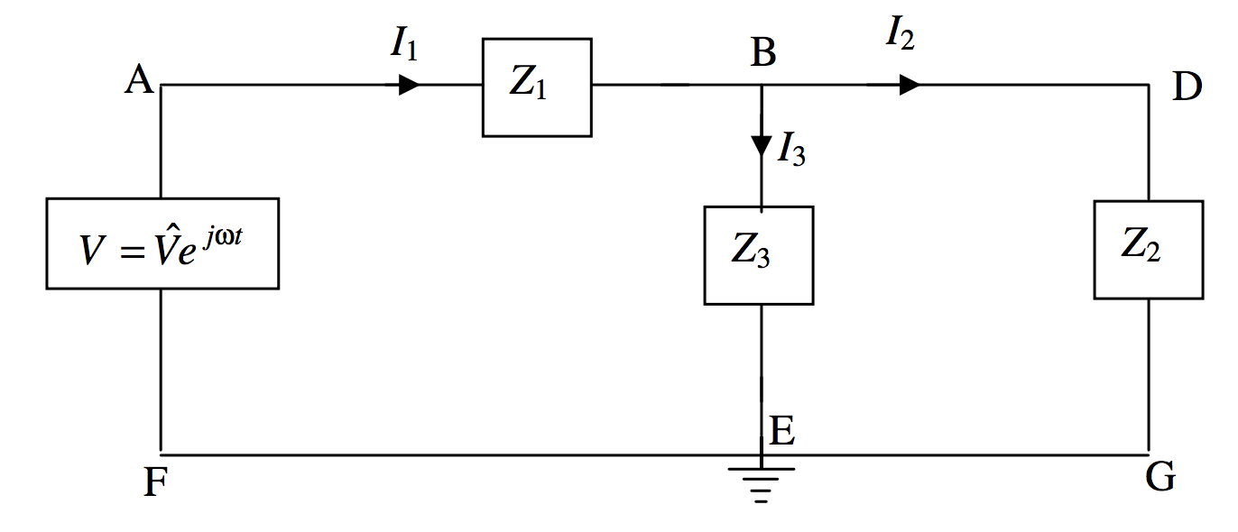
Each of the three impedances in the circuit could be various combinations of capacitors and inductors in series or in parallel, but, whatever the configuration, each could be written in the form \(R+jX\). Three Kirchhoff equations could be constructed as follows
\[\label{13.6.20}V=I_1Z_1+I_3Z_3\]
\[\label{13.6.21}V=I_1Z_1+I_2Z_2\]
\[\label{13.6.22}I_1=I_2+I_3\]
If I have done my algebra correctly, I make the solutions
\[\label{13.6.23}I_1 = \dfrac{V(Z_2+Z_3)}{Z_2Z_3+Z_3Z_1+Z_1Z_2}\]
\[\label{13.6.24}I_2 = \dfrac{VZ_3}{Z_2Z_3+Z_3Z_1+Z_1Z_2}\]
\[\label{13.6.25}I_3 = \dfrac{VZ_2}{Z_2Z_3+Z_3Z_1+Z_1Z_2}\]
Each must eventually be written in the form \(\text{Re}I+j\text{Im}I\), or \((G+jB)V\). For example, suppose that the three impedances, in ohms, are \(Z_1=2-3j,\,Z_2=4+2j,\,Z_3=3-3j\). In that case, I believe (let me know if I’m wrong, jtatum at uvic.ca) that Equation \ref{13.6.25} becomes, after manipulation, \(I_3=\dfrac{74+152j}{1429}V\). This means that \(I_3\) leads on \(V\) by 64º.0, and that the peak value of \(I_3\) is \(0.118V\text{ A}\), where \(V\) is in \(\text{V}\).
The potential at \(\text{B}\) is \(I_3Z_3\). Both of these are complex numbers and the potential at \(\text{B}\) us not in phase with \(I_3\) unless \(Z_3\)is purely resistive.
In composing a problem, you probably want all resistances and reactances to be of comparable magnitudes, say a few ohms each. As a guide, if you choose the frequency to be \(500/\pi \text{ Hz}\), so that \(\omega = 10^3 \text{ rad s}^{-1}\), and if you choose inductances to be about 10 mH and capacitances about \(100 \mu \text{F}\), your reactances will each be about \(10 \Omega\).
You can probably also compose problems with various bridge circuits, such as
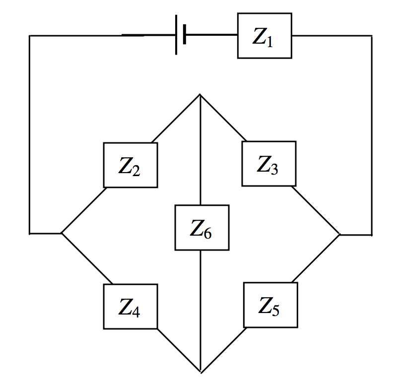
There are six independent impedances, so you’ll need six equations. Three for Kirchhoff’s second rule, to cover the complete circuit once; and three of Kirchhoff’s first rule, at three points. Good luck in solving them. Remember that, in an equation involving complex numbers, the real and imaginary parts are separately equal. And remember, as soon as a complex number appears in a denominator, multiply top and bottom with the conjugate. Alternatively, and easier, we could do what we did with a similar problem with direct currents in Section 4.12, using a delta-star transformation. We’ll try an example in Section 13.9, subsection 13.9.4.